


For Linear Translation Stages
1. Introduction
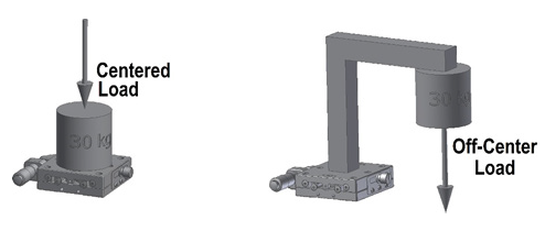
Linear translation stages are used for a variety of tasks but typically translate a payload over a distance with minimal lateral or angular deviation. In most cases, the payload is centered over the body of the translation stage (Figure 1). As long as the rated load capacity of the translation stage is higher than the weight of the payload, the stage will operate as expected. But what happens when the location of the payload is not centered over the body of the translation stage? How can we find out if an off-center, eccentrically loaded translation stage can handle its task? There are a couple ways to determine this, but first we need to understand how a stage works.
2. Translation Stage Basics
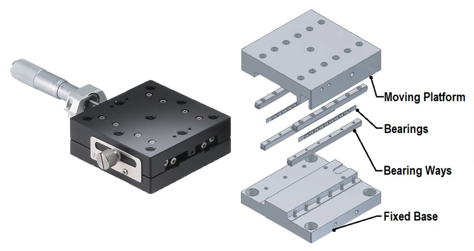
The main elements of a translation stage are fairly simple, consisting of a fixed base, a moving platform along with bearing ways, and bearing (Figure 2). When a translation stage carries a centered static load, the force of the load travels evenly from the top platform through the bearings to the base. If the load exceeds the capacity of the stage, failure can occur. The failure mode varies but is normally characterized by a localized plastic deformation of the bearing ways which causes the stage to lose its travel accuracy and parallelism.
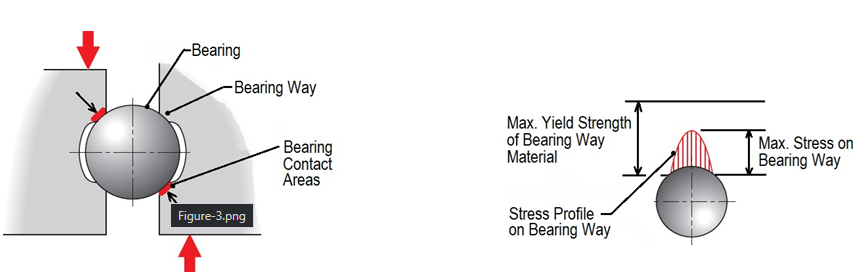
This denting results from stress levels at the contact area between the bearing and bearing way that exceed the yield strength of the bearing way material (Figure 3). Regardless of how a stage is loaded, whether normally or eccentrically, the most common failure mode is bearing way denting.
The presentation of most translation stage products includes a set of performance specifications like travel range, load capacity, and travel accuracy. However, it is surprising that considering the high number of applications requiring off-center loading, only a few suppliers include this value in their specifications. This omission has led many users to incorrectly assume that the standard load capacity of a stage applies to all types of loading configurations.
3. Estimating Off-Center Load Capacity
In the absence of an off-center load specification, an approximation can be made using the stage’s standard normal load capacity specification. Additional data is also needed: the actual payload weight, the distance the payload is from the center of the translation stage, and the spacing between the bearing ways. The basis of the approximation is a simple statics calculation of compound loading. A free body diagram, Figure 4, shows that the off-center (cantilevered) load, L, is supported by the two rows of bearings on the stage, R1 and R2.
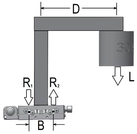
In this diagram:
- L is the load
- D is the off-set distance between the payload and the center of the translation stage
- B is the spacing between the bearing races
- R1 and R2 are the reaction forces acting at the bearing races
To estimate if a stage can support an off-center load, we start by assuming that each bearing race supports half the rated load capacity of the stage. Then we determine the forces acting on each of the bearing races, R1 and R2.
Finally, we compare the rated load per bearing race (PBRL) with the R1 and R2 forces. If both R1 and R2 are less than the per-bearing-race load rating, the stage will support the applied load. R1 and R2 are calculated from the free body diagram shown in Figure 4.
The equations derived from this diagram are created by knowing that since the stage is static, the sum of all forces acting on the stage is zero and the sum of all moments is also zero.
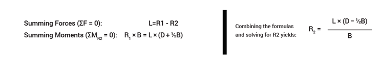
It is important to note that the force equation shows that the load on the two bearing ways is not evenly distributed; in fact, the R2 bearing way which is closest to the payload takes most of the load. Therefore, it is the R2 value that must be less than the per-bearing-race load rating (PBRL) of the stage to be able to adequately handle the load.
Example Calculation
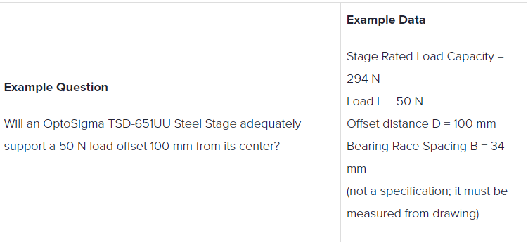
Example Calculations:
The per-bearing-race load rating of the TSD-651UU Steel Stage: PBRL = ½(Rated Load Capacity) PBRL = ½(294 N) = 147 N
Actual Load on R2 Bearing Race:
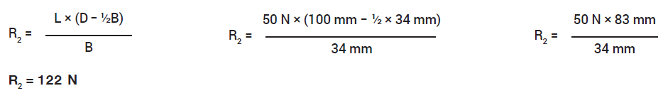
Example Conclusion
Yes. Since the R2 value of 122 N is less than the per-bearing-race load rating PBRL of 147 N, the TSD-651UU Steel Stage will be able to adequately support a 50 N load offset 100 mm from its center.
4. A Better Way: Using Published Specifications
There is an easier and more accurate way to make this calculation. As noted earlier, in spite of the high number of applications employing off-center loading, only a few suppliers include it in their specifications. OptoSigma is one of the suppliers that does. Using the OptoSigma stage from the previous example, TSD-651UU, we can find a published specification called Maximum Moment Capacity (MMC). The value is 14.7 N·m for the configuration we are using (roll).
All that remains is to calculate the applied moment load, MA, on the stage and compare it to the specification. Returning to the example, the moment applied to the stage is calculated by multiplying the load L = 50 N by the Offset distance D = 100 mm.
We convert 100 mm to 0.1 m to match the units in the specification. For the evaluation, we compare the MMC specification of 14.7 N·m with the applied moment, MA = 50 N × 0.1 m = 5 N·m. We arrive at the same conclusion as with the first example; that is, since the MA value of 5 N·m is less than the MMC specification of 14.7 N·m, the TSD-651UU Steel Stage will adequately support a 50 N load offset 100 mm from its center.
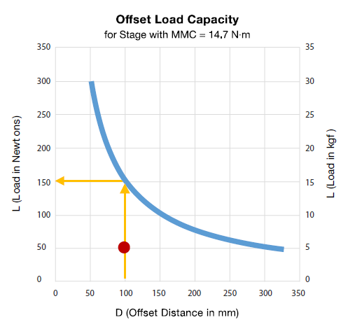
When the Maximum Moment Capacity specification is graphed, it can also be used to make quick estimates of off-center load capacity. We have seen that a moment load is calculated by multiplying load (L) by the offset distance (D). From the examples, this would be MMC = L × D. Since MMC is provided as a specification and we know the moment equation, it can be graphed (Figure 5). The graph’s x-axis shows offset distance and the y-axis shows load.
The actual curve on the graph represents the limit of the stage’s off-center load capacity. Using the graph to solve our example problem, we locate the offset distance (100 mm) on the x-axis and find where this intersects the curve. From this we see that the maximum load would be ~150 N (or 15 kgf). Since the load in the example is 50 N (indicated by red dot on graph), we have the same conclusion as before; the stage will work. Basically, any combination of “offset distance” and “load” that yields a coordinate on the graph that is on or below the curve would be within the capacity of the stage.
5. Conclusion
Linear translation stages are mostly used in cases where the payload is centered and it is easy to determine if it will hold up in these cases. Now, with off-center loads we can determine if the stage will work. Either by calculating an estimate based on normal load capacity or by using an actual maximum moment capacity specification, we can be confident in our selection of the right translation stage for the job.
This content was sourced from our partner OptoSigma.
Other Blogs/Articles that may be of interest:
- Why is Mid-IR Light so Important?
- Engineered Point Spread Functions (PSF) for Single Molecule Localisation Microscopy (SMLM)
- Nanoscopy for less than £100k?
- Understanding the jargon of LCOS Spatial Light Modulators (SLMs)
- Spatial Light Modulator Applications
Speak to our engineers and contact us here: